Create a Battery Powered ESP8266 Dual Push Button

So - it's been a year since I last wrote an article on my blog, and funnily enough this on the same topic as my last article- An Amazon Dash Button Clone.
As I've had the Christmas break, I decided to have another go at the WiFi button that controls my lights and fan. However, this time making it battery powered using an 18650 battery.
Why?
The push button I made last year using an ESP-01 worked has worked for the most part. And thinking about it, I probably could have looked at integrating deep sleep with ESPEasy. However, over the last year I've been trying to learn how to code better and decided this was a good opportunity to make a simple push button Arduino sketch.
Features
- Two separate buttons being used with the ESP-01, and no separate GPIO expander.
- The second button in this case must be held after pushing the first button. This causes the second button pin to go "HIGH", allowed a different message/event to be triggered. Ideally the second button could be used standalone but this wasn't a big deal in my case.
- Reset button used with ESP-01 without having to solder any extra wires to the ESP8266 for deep sleep
- Push Button using a power bank that still works as a power bank ;-)
- MQTT message sent when button pushed.
Parts used:
- 1x 18650 Battery
- Push Buttons
- 18650 Power Bank Case - Use only one of the battery slots. ESP in the other slot.
- ESP-01 DHT11 Temp Sensor board - Later remove the temp sensor to instead use the push button.
- ESP-01, and USB Programmer for it.
- Various tools and solder.
The crux of our Arduino sketch is built around booting our ESP, running our code, then going into Deep Sleep. We use the RST (Reset) pin connected to our Push Button to trigger this process again. In the case of my project here, we actually use the RST button already connected on the ESP-01 DHT11 Temp Sensor board rather than having to make our own circuit or use perf board.
This means we don't have to complete the painful task of soldering a reset wire on to the ESP8266 chip itself.
Why the Power Bank, and DHT11 Temp Sensor board?
These are both great questions. Ultimately I wanted a quick, simple, polished solution. Some may choose to 3D print a case for something like this, but I didn't want to take the time to learn how to 3D print when I already had useful parts on hand.
You could make your own case, and use something like the TP4056 charging module, however the power bank case and electronics was only ~$2USD which seemed like a better solution to me. The added benefit is this project is still a usable power bank once completed! (if desired..).
And the DHT11 Temp sensor board?
I chose this because I had a couple of these on hand, along with a couple ESP-01s. The primary benefit of the ESP-01 compared to something like the NodeMCU or Wemos D1 Mini, is that it's ultimately less electronics. This means there's less passive components to power or have to consider with a battery powered project. What's the actual stats around this? I don't have any on hand, but I encourage you to google this if wanting to take on a similar project. If I didn't have the ESP-01, I probably would have still tried this with the Wemos D1 Mini.
The DHT11 sensor board means we already have a board that provides a 5V to 3.3V built in voltage regulator. It also has a RST button we can un-solder and then attach our push button to for bringing the ESP out of deep sleep. I also like the DHT board because it meant I didn't have to make a perf board with ESP header and separate power regulator; it was just all on it already.
How does the code work?
- First we decare which libraries we need. In this case, PubSubClient is used for the MQTT communication
- As per most ESP projects, configure your SSID/Pass and other info such as MQTT server IP address (this guide assumes you already have as server set up).
- Configure Static IP address. If you're running this on something like an 18650 battery, it's highly recommended to use a static IP address. This is because it saves precious "active" time when the ESP is awake which saves battery consumption. A static IP can save anywhere from a few milliseconds, to several seconds. Note: The code is correct. IP address is specified here with commas, and not dots.
- Next we declare which pins we're interested in. The ESP-01 only has a couple usable GPIO pins (I think you can use others if you sacrifice serial debugging etc) being GPIO 0 and 2.
- This became difficult because button states matter on boot up depending on whether pins are in a HIGH or LOW state can trigger things like "config mode", instead of actually running our code.
For more on usable GPIO pins, especially on the ESP-01, the following Instructable is really useful:
https://www.instructables.com/id/How-to-use-the-ESP8266-01-pins/
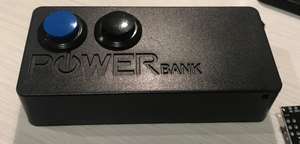
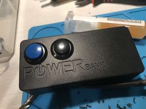
- In the case of this project, we use The RST pin connected to our main button (blue button in the image), and connect the second auxiliary button to GPIO 2. This is because GPIO 2 can be LOW or HIGH on boot and not trigger something else like Config/Download mode.
- If only the Blue Button is pressed, the ESP will send the following MQTT message on boot:
ESP-Push-Button/btn1 - If the Auxiliary Button (Black button in picture) is pressed after the ESP has been reset, this will trigger MQTT message
ESP-Push-Button/btn2being sent. - Unfortunately the black button is not standalone. It can't send "btn2" message on its own, and needs the blue button pressed first to pull the ESP out of deep sleep. I normally just hold both buttons to trigger "btn2" message.
- The code below also ensures the ESP will go back into Deep sleep after 5 failed attempts to either connect to the assigned SSID, or fails to send the actual MQTT message.
The Code
If you use platformio with VS Code or Atom, you can use the above platformio.ini config for building the project.
Let's build the project!
I first had to figure out whether there would be enough space inside the Power Bank's case. The next couple of pictures give you an idea around where I've put the buttons, along with getting the ESP to fit:
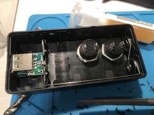
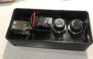
As you can see, I've soldered a couple wires directly to the USB + and - for powering the ESP.
I've also de-soldered the DHT11 from the Temp board, since we won't be needing that. Instead we'll use the GPIO Pin the DHT11 was connected to for our second button.
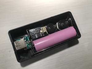
Before soldering the buttons in, and making any final adjustments, I ensured everything would be able to fit in nicely. This meant having to remove some of the plastic in the case around the battery, and where the ESP would be sitting.
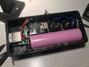
I then connected the Blue wires (Blue Button) in the image above to the reset pin solder joints on the DHT 11 Temp board. The Black wires (for the Black Button) are connected to the solder pins originally connected to the DHT11 on the Temp board.
For final measure, I used some hot glue to secure the battery wiring.
Destroy all LEDs!!!
LEDs on the ESP, Battery charger, and DHT Temp board consume a huuuuuge amount of power. For DIY, you can either try unsoldering the LEDs, or opt for the "simpler" method of getting in a fight between a screw driver and the LEDs. Once the LEDs are destroyed, power consumption (especially in deep sleep) will dramatically drop!
Results
I've used this for turning my lights and fan on once or twice every day for about 6 weeks. So far no need to recharge. I'm expecting it'll probably last about a year.
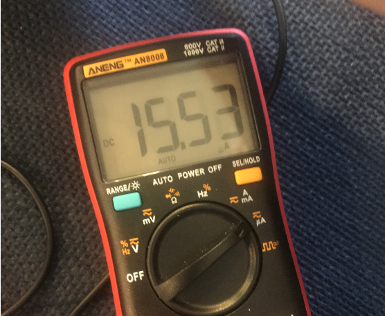
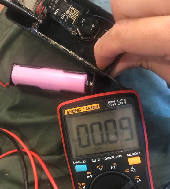
In terms of actual consumption, my ANENG AN8008 multimeter is showing 0.09 µA in deep sleep, and 15.53µA when active. Somewhat insane stats, so I'm slightly skepticle, but here's a couple pics showing this:
Now that it's built? what next?
Ensure both buttons trigger the relevant MQTT messages. My home server for example is using Mosquitto. I can use matt@server:~$ mosquitto_sub -v -t \#to verify all in-coming MQTT messages.
Configuration of home automation tools such as Home Assistant are outside the scope of this article. I have however touched on this with Home Assistant in my previous article.
Enjoyed this article? Made a similar project? I'd love to hear in the comments :-)

Comments